My friend and I are in the process of swapping an early 1989 7MGTE into a 1990 Supra. The wiring harness off of the blown engine that was in the 1990 Supra has several broken connectors and is in overall poor shape. The harness on the early 1989 engine, however, is in great shape. We want to swap this engine with harness and ECU into the 1990, and had set out to find what is different between the 2 harnesses primary connectors- M1, B1, B2, B3, B4, C1, and U1 plugs (as referenced by the TEWD)- so that this harness will interface with the rest of the car properly. For those of you that do not know this already, early 1989 engine harnesses are very similar to pre89 harnesses; ours has gray plugs, but they are the same shape and pin configuration as yellow plug harnesses.
The following information is what I have uncovered doing some reading in the TEWD and researching online. The tables are set up so that someone with a Yellow Plug harness can remove the pins, in order, and place them in the correct location of the Gray Plugs. Some plugs are the same between pre89 and 1991. The pinout of these are included for reference.
Please note that most of this information has been retrieved from the 1987 TEWD and from Supra_Dave's 2JZ swap wiring write-up
here over at Supras.nl
HTML tags are used so that I didn't have to modify my pre-formatted text lol
M1 Plug
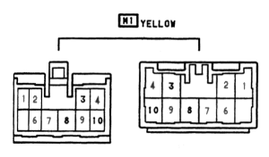 Pre89 Plug Configuration
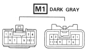 1991 Plug Configuration
HTML Code:
pre89	1991
Pin#	Pin#	Function
1	1	Backup Light Switch Signal
2	2	B+ for Backup Light Switch and B+ for A/C Water Valve VSV
3	3	SPD Signal from Combination Meter
4	4	RPM Signal for Combination Meter
5		Turbo Indicator Light Signal for Combination Meter
6	6	Water Temperature Gauge B- for Combination Meter
7	7	Oil Pressure Signal for Combination Meter
8	9	"W" Signal for Check Engine Light
9	10	Water Temperature Signal for Combination Meter
10	11	Signal from Defogger Relay
	8	-- Blank --
B1 Plug
 Pre89 Plug Configuration
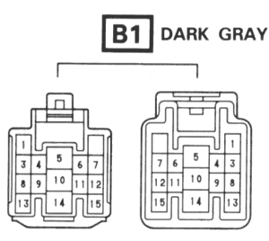 1991 Plug Configuration
HTML Code:
pre89	1991
Pin #	Pin #	Function
1	1	A/C Water Valve VSV
2	B2 #17	L3 Signal ECT / ECU
3	B2 #18	L2 Signal ECT / ECU
4	B2 #19	L1 Signal ECT / ECU
5	3	FP Signal (Check Connector)
6	4	EFI Circuit Opening Relay Coil
7	5	A/T Circuit Opening Relay Coil
8	6	Fuel Pump Control Relay
9	7	Circuit Opening Relay B+
10		--Blank--
11	B2 #7	"N" Signal - A/T Indicator Switch
12	10	Neutral Start Switch
13	11	A/C Amplifier
14	B2 #6	TEMS Check Connector
15	8	NSW Switch to Cruise Control Clutch Switch (M/T)
16	9	Check Engine Light
17	14	Ignition B+
18	12	Theft Deterrent Horn Signal
19	B2 #4	Headlight Idle Up Signal
20	N/A	Coil to Super Monitor Computer
21	N/A	Super Monitor Computer
22	N/A	Super Monitor Computer B-
B2 Plug
 Pre89 Plug Configuration
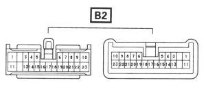 1991 Plug Configuration
HTML Code:
pre89	1991
Pin #	Pin #	Function
1	8	"2" Signal ECT
2	B1 #15	Spd Signal Cruise Control / ECT
3	5	Solenoid 2 for ECT and Cruise Control
4	B3 #5	RR B- Signal for ABS
5	B3 #1	RR B+ Signal for ABS
6	16	O/D 1 Signal ECT / Cruise Control
7	13	"L" Signal ECT
8	14	Solenoid 1
9	15	Lockup Solenoid
10	B3 #7	"P" Signal for ABS
11	B3 #6	Speed Signal for ECT from ABS Computer
12	B3 #2	PSEN for ABS
13	20	IDL Signal from ECT / TCCS
14	21	DG Signal ECT for Check Connector
	1	Air Bag Signal Check Connector
	2	Oil Level Signal Light (European Models)
	3	B- for ECT Speed Sensor Solenoid
	11	TC Signal for Air Bag / Cruise Control
B3 Plug
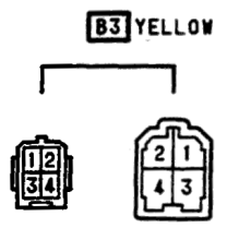 Pre89 Plug Configuration
 1991 Plug Configuration
HTML Code:
Pre89 N/A Only
pre89	1991
Pin #	Pin #	Function
1	B2 #9	Heater Signal for Sub Oxygen Sensor
2	B2 #10	Oxygen Sensor from Sub Oxygen Assembly
3	B2 #22	E11 Signal for Sub Oxygen Assembly
4	B2 #23	Seal / Mass for Ox Signals

All Others
pre89	1991
Pin #	Pin #	Function
B2 #5	1	RR B+ for ABS
B2 #12	2	PSEN for ABS
	3	-- Blank --
	4	PPS Solenoid
B2 #4	5	RR B- for ABS
B2 #11	6	Speed Signal for ABS from ECT Computer
B2 #10	7	"P" Signal for ABS
	8	-- Blank --
	9	-- Blank --
	10	PPS Solenoid
B4 Plug (Pre89 Models ONLY)
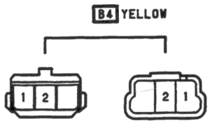 Pre89 Plug Configuration
HTML Code:
pre89	1991
Pin #	Pin #	Function
1	C1 #6	A/C Water Temp Switch no. 2
2	B1 #13	A/C Water Temp Switch
C1 Plug
 Plug Configuration
HTML Code:
pre89	1991
Pin #	Pin #	Function
1	1	Battery Signal from 15A EFI Fuse
2	2	M-Rel Coil Signal from ECU
3	3	B+ from 15A Haz / Horn Fuse for Theft Deterrent Horn
4	4	B+ from EFI Main Relay (via 15A EFI Fuse)
5	5	B- for Air Flow Meter Switch
6	6	A/C Water Temp Switch no. 2
U1 Plug
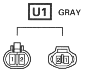 Plug Configuration
HTML Code:
pre89	1991
Pin #	Pin #	Function
1	1	Theft Deterrent Horn Signal
2	2	B+ for Theft Deterrent Horn
***NOTE*** The following Pins are found on the 1991 harnesses, but are not found on pre89 harnesses:
HTML Code:
B2 Plug

1	Air Bag Signal Check Connector
2	Oil Level Signal Light (Typically found on European Models)
3	B- for ECT Speed Sensor Solenoid
11	TC Signal for Air Bag / Cruise Control

B3 Plug

4	PPS Solenoid
10	PPS Solenoid
Hopefully this information will help someone understand their engine wiring, and assist in completing a nice, clean engine swap
